Site & Civil Design
Wells, pipelines, structures, and site conditions
Production Wells
Two new deep groundwater wells will be constructed on the project site, one in each phase. Each well produces approximately 2.25 MGD under normal operations. The wells alternate pumping cycles to reduce wear and minimize cumulative drawdown on the aquifer.
Wells are spaced to prevent overlapping drawdown cones. Design is based on reference data from the nearby Well 6 at Anita B. Smith, which operates under similar groundwater conditions.
Piping
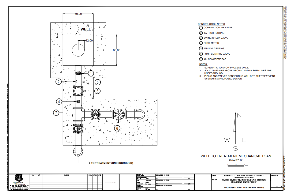
Three pipeline segments connect the wells, RO facility, and existing distribution system. All pipelines are installed underground in existing rights-of-way or utility easements.
| Segment | Flow | Diameter | Material | Velocity |
|---|---|---|---|---|
| Well to RO Facility | 2.5 MGD | 12" | CML&C Steel | ~3.87 ft/s |
| RO to Distribution | 4.5 MGD | 24" | CML&C Steel | ~3.48 ft/s |
| Brine Disposal | 0.5 MGD | 8" | CML&C Steel | ~1.16 ft/s |
Velocities are within accepted industry guidance (~3 ft/s for production, up to 10 ft/s for flushing). All pipe is cement mortar lined and coated steel per AWWA C200.
Pump Station
The facility uses VFD-controlled (Variable Frequency Drive) horizontal split-case pumps. Pump speed adjusts dynamically to match system demand, providing precise flow and pressure regulation while improving energy efficiency compared to fixed-speed alternatives.
Treatment Building
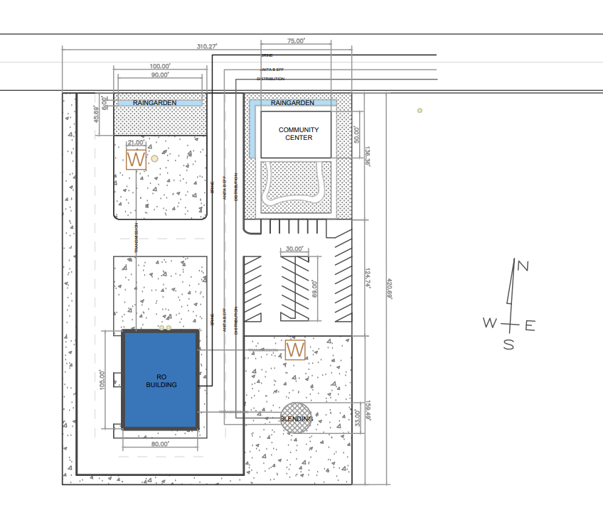
The RO treatment process is housed in a steel-framed building designed to accommodate all six skids at full build-out, with a crane system overhead for maintenance access.
Geotechnical Conditions
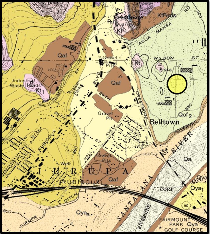
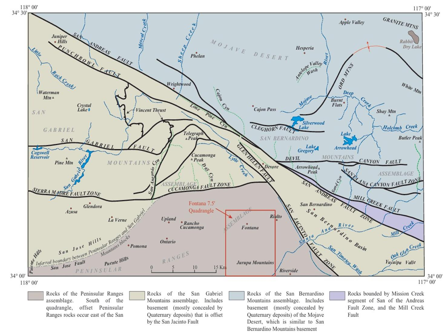
The project site is located at the southeastern base of the Jurupa Mountains, underlain by Pleistocene alluvial fan deposits. The soil consists primarily of sandy loam and fine sand with low expansion potential and good drainage.
Seismic
No active faults cross the site. Nearest fault is the San Jacinto Fault. Liquefaction susceptibility is moderate.
Flood Risk
Outside the FEMA 100-year flood zone with low erosion risk.
Foundation
Shallow spread footings with estimated 2,000–3,000 psf bearing capacity. Subsurface exploration is required before final design.
Hydrology
The site has very low runoff conditions due to the dry climate and small site area. The 100-year design storm intensity is 0.2 in/hr. Soil is predominantly high-infiltration (71% Class A, 29% Class C).
| Condition | Peak Discharge | Travel Time |
|---|---|---|
| Pre-development | 0.018 CFS | 12.5 min |
| Post-development | 0.030 CFS | 8.5 min |
Peak flows are extremely low. The on-site rain garden is sufficient to accommodate all runoff, so no additional stormwater infrastructure is required.